


Page 61 - FDMAsia MarApr 2025
P. 61
MATERIALS         59
         www.fdmasia.com | FDM ASIA MAR/APR 2025


          were supported  at both ends and  the loading points, and   hypothesis of mechanically linked beams without considering
          were spaced six times more than the panel thickness (6 h)   shear deformation. As suggested by Brandner et al., Equations
          between the center and either end of the opposite support.   were used to calculate the bending stiffness by all three
          The load was gradually increased, reaching a peak in about   methods.

          300 ± 120 s.
            The extensometer linked to the testing apparatus determined   Finite Element Modelling
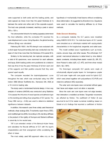
          the total deflection, while the connected PC recorded the   As a composite material, the CLT panels were modelled
          load–displacement curves. Using Equation, the global bending   using ANSYS 2019 R13. The individual layers of CLT panels
          stiffness (EImg) was calculated.                   were simulated as an orthotropic material with varying elastic
            Following EN 16351, the RS strength was evaluated with   characteristics in the longitudinal, tangential, and radial axes.
          a short-span four-point bending test was conducted over the   The model omitted wood imperfections such as knots,
          span of nine times more than the thickness of the panel (9 h).   cracks, annular rings, and other issues. The orthotropic CLT
            Similarly to the bending test, ten replicate samples, with   panels’ mechanical behaviour is determined by nine distinct

          a total of 60 specimens, were examined for each adhesive   elastic constants, including three elastic moduli (EL, ER, ET),
          and layup. Both loading points were positioned at a distance   three Poisson’s ratios (vLR, vLT, vRT), and three shear moduli
          that was three times the panel thickness (3 h) from each end   (GLR, GLT, GRT).
          of the supports and their position ensured that they were   The three-layer composite CLT panels were made of
          spaced apart equally.                              orthotopically aligned poplar layers for homogenous poplar
            The computer recorded the load–displacement curve   CLT and outer maple with core poplar wood for hybrid CLT,
          throughout the test, which was conducted using the UTM   which were joined together with polyurethane (1C-PUR) and

          Instron 5882 (Illinois ToolWorks Inc., Norwood, MA, USA) at   melamine adhesive (ME) separately.
          a 10 mm/min loading rate.                             The outer and core layers were connected without gaps;
            The study used a randomised factorial design. A two-way   their faces and edges could not slide or separate.
          analysis of variance (ANOVA) was conducted using Statistica   Since the outer and core layers were not edge bonded,
          13 to assess the influence of wood species and adhesive type   their interaction is modelled as friction. Tangential movements
          on the bending and rolling shear properties of CLT panels. The   are affected by friction. The coefficient of friction (f) was
          Tukey HSD test (p < 0.05) was used to determine statistical   assumed to be 0.5 for easier numerical modelling, based on
          significance between datasets.                     Dobeš et al.’s findings that reported a coefficient of friction
            In addition, this research used three widely used theoretical

          methods: shear analogy (SA), Timoshenko beam theory (TBT),
          and modified gamma (MG). According to SA, bending stiffness                                         Theron Burger
          is the product of the rigidity of the layer and Steiner’s stiffness
          in proximity to the neutral axis.
            TBT is an extended version of the Bernoulli–Euler theory
          and calculates the flexural stiffness of CLT with the layer’s
          characteristics and their arrangement while considering the

          effect of shear.
            The  most  widely  used  MG  approach relies  only  on  the

